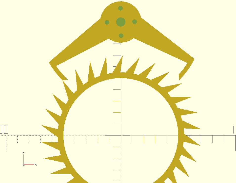
I recently built a
Graham escapement
for Hackaday's
1Hz challenge.
Not a whole clock, just the escapement.
It's hard to justify deep investment into 17th century tech, but the contest was a
convenient excuse to toy with something that has fascinated me since
I was a kid as long as the time, money and effort invested was minimized!
I won't win the contest. There were some impressive entries.
Anyway, following is a brief overview of how I arrived at a working
design through only logic and intuition and without getting bogged down
in the physics.
Graham escapement operation in ~450 words
Technically, the pendulum regulates the escapement mechanism, and the escapement
mechanism powers the pendulum.
It's a collaboration.
Everyone is familiar with the regulation; it's both visible in the swinging
pendulum and audible in the escapement: tik-tok!
The "powering" occurs silently and somewhat invisibly in only milliseconds of
each swing during which the escapement wheel and armature convert the
potential energy of a weight into kinetic energy in the pendulum.
The armature delivers very brief, practically invisible,
impulses to the pendulum
without which mechanical friction and air drag would eventually
halt the pendulum's swing.
The two roles of the escapement mechanism are coupled in the precise shapes
of and angles between the impact and impulse faces of the arms and, of
course, the overall rotational constraints on those faces.
The (conventional) shapes of these faces, specifically their corners, result in
six phases of operation, three per arm, delimited by discontinuities.
The two arms interact with the teeth of the wheel symmetrically, so
it's really only necessary to describe three of the phases.
Phase 1: Impact
A tooth of the (clockwise-rotating) escapement wheel hits the left impact
face (tik!), commencing phase 1.
The pendulum may or may not be stationary (at its maximum amplitude) at
the time of impact, but because the impact face by design coincides with
its own rotational arc it allows the pendulum to rotate both directions
with only mechanical friction, and ideally very little of that, between the tooth and face.
In particular, the escapement wheel cannot transfer any much torque
to the arm while an escapement wheel tooth is in contact with the impact face.
(In fact, an infinitesimal amount of torque is transfered thanks to the friction,
but nevermind!)
Eventually, the pendulum and thus the arm will reverse direction and the
tooth tip will slide down the impact face and around the corner onto the
impulse face, commencing Phase 2.
Phase 2: Impulse
As long as:
the tooth tip is sliding along the impulse face and
the angle between the impulse face and the tangent to the tooth's circle
of rotation at the contact point is >0 and <90...
...the wheel delivers sufficient torque to the arm to keep the pendulum swinging.
It is only milliseconds of torque, an "impulse" indeed.
Eventually it slides off the interior corner of the impulse face, commencing Phase 3.
Phase 3: Free fall, er, spin
For a few milliseconds the escapement wheel is released from all constraints
and the suspended weight, acting through the pulley, applies torque to actually
accelerate the escapement wheel.
...until a tooth on the right side strikes the right impact face (tok!),
and the process repeats (with directions reversed) on the right side.
The animation below shows some of this.
(It omits the sliding of teeth on the impact faces.)
This animation is composed of static frames generated using my actual
OpenSCAD design files.
It is only meant to highlight the relative positions of teeth at the
instants of discontinuity—that is, at the corners of the impulse faces.
You might notice that the animation is not symmetric: there is a frame with a tooth
centered in the left impulse face, but no corresponding frame with a tooth centered
in the right impulse face: Why? Laziness.
In an animation generated from a physical simulation the
impulse faces would rock further both into and out of the teeth and obviously
the rotation would be smoother.
They were composed into a GIF by ImageMagick: convert -delay 25 -loop 0 *.png ticktock.gif.
Design
The precise timing, and feasibility, of the preceding sequence
of events depends on soooo many parameters, geometric and physical, which is why
the escapement could be fodder for so much physics modeling.
I doubt
George Graham
went through that exercise.
He likely arrived at his escapement design like I am: intuition and trial and error.
(Anyway, I'm not going to attempt
circumnavigating the globe under sail based on my design.)
First, all dimensions were initially constrained by the maximum diameter
escapement wheel that I could print in my FlashForge.
The larger the wheel, the less impact printing imperfections would have
on its operation.
My FlashForge's print bed is 150x200mm, so all my design work started assuming an
escapement wheel with an (outer) radius of 70mm.
Let's put a few parameters to rest without brooding:
How many teeth on the escapement wheel? 30. Many mechanisms I've seen
seem to favor that number, maybe because it's half the 60s in a minute!
How many teeth are spanned by the impulse faces? ~7.5. Why? With 30
teeth that leads to a ~90° span, and right angle are often Good!
We'll remove the "~" below. Ok? Ok. Move on...
The impact faces of the Graham escapement wheel are basically what
defines this design: they must coincide with the rotation of the
face, so that's done.
The escapement wheel's teeth have overhang to insure that only the tips
of the teeth are in contact with the impulse and impact faces. How much?
I dunno. 2° sounds good. Moving on...
The hard(er) stuff
All the big remaining questions concern the impulse faces:
their sizes
shape (linear or curved)
geometric relations to other reference points in the mechanism including:
the axes of rotation (of wheel and armature),
tangents to the tooth circle, etc.
escapement wheel teeth tips
Because of this some of the following heuristics might not be correct, so
don't take the following as authoritative.
(Actually, that advice applies to everything everywhere all the time,
not just the following!)
Constraints are your friends
...because they answer questions.
According to the Airy condition
"the best place to apply the impulse to keep the pendulum swinging was at
the bottom of its swing, as it passes through its equilibrium position."
So lets insure that when the pendulum is vertical—that is, at those two
instants in time—whatever tooth is in contact with either impulse face,
it is centered on that impulse face.
Symmetry is an even better friend
It makes questions redundant.
The Airy condition applies to both arm's impulse faces in both rocking
directions, and
we want the same impulse delivered in both directions(?)
#1 is provable, but is #2 even correct?
It was obvious to me...before actually thinking about it.
What would actually ensue from different impulses?
Asymmetric 1-ε and 1+ε "seconds?"
Could a mechanism be designed that would even deliver (significantly) different
impulses to each side and continue functioning??
Answers to these might be obvious to some.
They're not immediately obvious to me.
Anyway, in the absence of any reason favoring differing impulses,
simplicity dictates they be the same, and
the rotational symmetry of the teeth implies both sides of the arm should
interact with the teeth identically.
Nevermind.
Some people like crystals.
I like symmetry!
My magic is clearly superior.😀
The Airy condition implies that both impulse faces' centers should
lie on the circle containing the tips of the escapement wheel's teeth when
the pendulum is vertical.
The goal of symmetric impulses means the lever arms should have equal lengths.
This much is clear.
Four final questions
What should be the axle spacing between the armature and wheel?
We've established a tooth should be centered on an impulse face when the pendulum is vertical.
It is intuitively obvious that this can only apply to only one tooth
at a time or the whole mechanism would be locked motionless.
So exactly where should the opposite impulse face be when one impulse face
is centered on a tooth?
What should be the angle between an impulse face and the tangent to the teeth
circle at the point of impace be?
(...assuming as I am that the impulse faces are flat!)
How wide should the impulse faces be?
Axle spacing
Intuitions (which might be wrong) of maximum power transfer through torque suggest
to me that a 90° angle between the two lever arms when a tooth is centered on
an impulse face is Good.
Maybe? Is it? ...Bueller?
Let's go with that.
Impulse face span
"Half-way between" is the maximum-entropy answer corresponding to my uncertainty.
I really doubt this is dynamically optimal, but it's a fine starting point for trial and error.
Impulse face angles
This is where maximum power transfer definitely applies.
Without calculations, 45° seems like it might yield maximum power transfer, but
friction worries led me to reduce that ever so slightly...to 42°.
I know: intuiting a 3° delta is absurd.
Impulse face sizes
Eh, I went with 7mm initially, and that did not work...at all.
Backed off to 5mm, and that did!
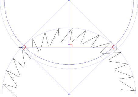
The following Asymptote-generated diagram summarizes the above rationale,
and OpenSCAD files here will generate STL for a wheel and armature that can be 3D printed.
The short black lines, left and right, are the impulse faces of the armature, arguably
the most important reference points in the figure.
Notice that they deviate 3° from horizontal and vertical thanks to my choice of 42°
between the faces and tooth-circle tangents.
Obviously, this isn't CAD; it shows only the geometry relevant to the above rationale:
the escapement wheel's teeth and the impulse face positions.
It elides the impact faces, too, because there is no mystery to them: they must
be the left external and right internal bounds of the armature, and they must
be curves coincident with the internal and external arcs of the impulse faces.
The CAD obviously includes detail elided here: the armature outline and hub of the escapement wheel.
The actual physical armature only serves to keep the distances between the impulse
faces and their center of rotation fixed.
References
Hitting your fav search engine with "plans for deadbeat escapement" will yield months of reading.
A very small sample...