The joys of an old house in Rain City
Of course I have a water problem in my 1921 Seattle bungalow.
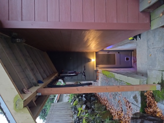
The basement is accessed from an outside stairwell. An addition
was built that included wide eaves which now protect this stairwell
from direct rain (left image below), but it wasn't always so.
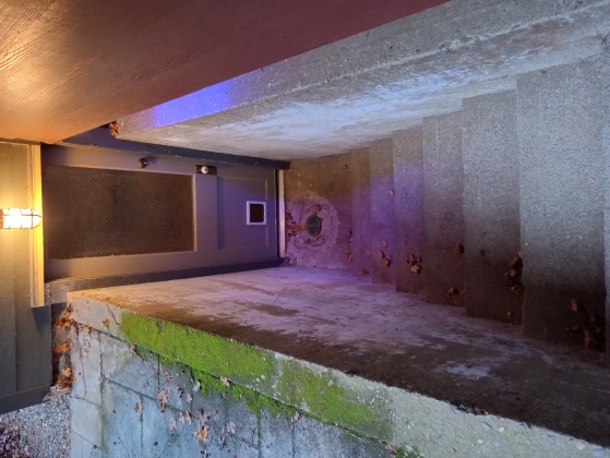
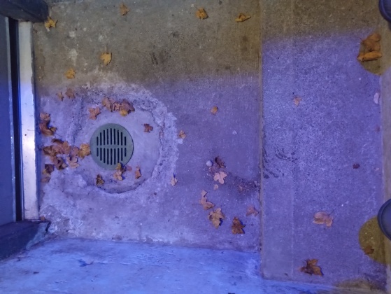
At the bottom of the stairwell (center and right images) is what appears to be a drain,
presumably part of the original build when the stairwell was
uncovered and obviously meant to preclude water from pooling at the
basement door and subsequently seeping into the basement. This is
Seattle after all, and the myths aren't myths: it might rain greater
volumes elsewhere,
but on average Seattle is rained on one out of every two days.
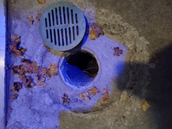
Wherever this drain used to lead, it doesn't anymore. I lowered
a camera, and there seems to be a small cavity with no outlet
under the basement floor. Lovely.
Yes, the stairwell is protected from direct rain, but water goes
where water wants to go.
When atmostpheric rivers
arrive in Seattle (autumn and winter) and it rains for days
weeks, the ground becomes saturated and water begins to seep into the
stairwell from cracks in the stairs and the retaining wall.
Presumably it's also seeping directly into the cavity from underground.
Eventually the hole beneath that drain cover fills, overflows
into the bottom of the stairwell and then into the basement makerspace.
I like dry makerspaces.
This has to stop.
The seepage is fortunately slow but persistent.
The inflow of water is probably only a few gallons/hour—I haven't measured,
but it can go on for days even after rain has ceased.
Fortunately, although the house's foundation shows every one of its 100+ years,
this is the only place from which water enters the basement, so I just
need to pump it out of the hole faster than it arrives.
This is not a new or unique problem
Water, the universal solvent and promoter of corrosion and rot, is the enemy
of everything not alive.
This is an old problem of civilization, and as one would expect in a market
economy, technology has been created to address it.
Automatic pumps of all kinds (and qualities) are available, many
specifically targeted at homeowners.
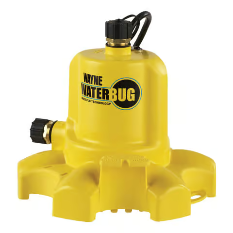
I used this one during an earlier event, but it's
not automatic. I had to man the switch, and I wearied of that and eventually let
the basement flood.
Surely there's a water-sensing, automatic pump out there I can just buy(?)
Maybe not...
What we have here is a failure to communicate
not a pumping problem.
1001 different pumps are available that can handle my modest pumping
requirements (maybe 10 gal/hr).
It's a control problem.
Automatic pumps incorporate some kind of water depth sensor.
According to the marketing for the
WAYNE WaterBUG® AUTO,
"The automatic switch turns the pump on when there
is 1.625″ of water and then off when the water is gone."
That's great, except that as soon as there is ≥ 0.5" of water in the bottom
of my stairwell, it has already started flowing into the basement.
It will never reach 1.625"!
Automatic pumps sense depth
(as opposed to merely water presence) because pumps must be
primed.
Submersible pumps are typically "self-priming," but enough water must be
present to do that.
I looked at a lot of pumps, and I suspected this would be a showstopper
for most of them.
Some of them might have worked, but I'm old enough to know
what marketing claims are worth.
I need to keep the water to essentially zero depth in the
stairwell which means I need to sense its depth in this hole...
...and pump it from there before it reaches the top.
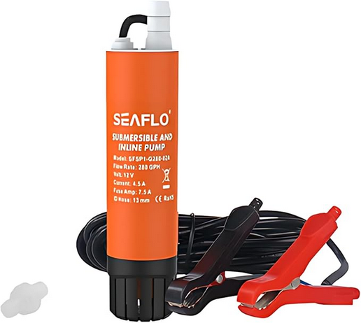
I found a great little 12V submersible bilge pump
on Amazon that can move gallons/minute and can be lowered into the hole.
...which leaves sensing and control.
I need sensor(s) and a controller that:
- can sense water level in
- a 15cm wide by 60cm deep hole
- and turn my pump on and off appropriately.
Looks like I have a new project...
What do I mean by "appropriately?"
Starting an idle machine, any machine, involves acceleration which,
in turn, involves stresses and strains.
Turning it off is not fundamentally different, but potentially incurs another cost:
the energy you've put into the machine has to go somewhere.
If deceleration isn't passive like coasting--that is, if some sort of
braking is involved--that's an additional element of
wear and tear.
All of this is to say: machines don't like to be turned on and off any
more frequently than necessary.
Also, not only must pumps be primed they usually must not be run dry.
Pumps (specifically, their motors) are designed to operate with a
particular load.
Running a pump dry (without moving water) for very long can burn out the motor.
So these pump constraints add a couple more requirements.
Finally, I'd like the results to be easily deployed, not installed.
I want to be able to put it in place during one of the relatively infrequent
multi-day deluges and then removed entirely the rest of the year so
it's not blocking entrance to the basement.
And, of course, I want it to be both reliable and cheap inexpensive. 😏
- Sense water level in
- a 15cm wide by 60cm deep hole.
- Control a 12V pump (incidentally drawing 5A peak, <<5A steady state).
- Minimize power cycling of the pump.
- Be easily deployable.
- Cost not a lot.
Design
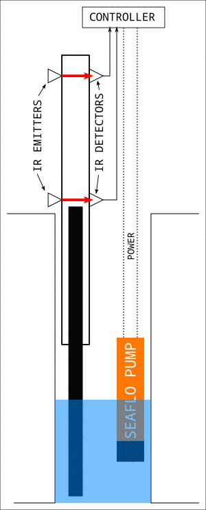
The animation below summarizes what I came up with, and it
hardly warrants a more careful drawing since it's
easily adapted to different specific physical dimensions.
Concept
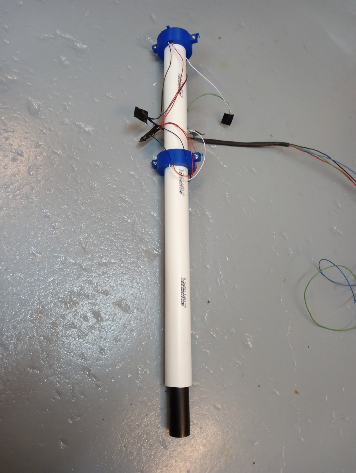
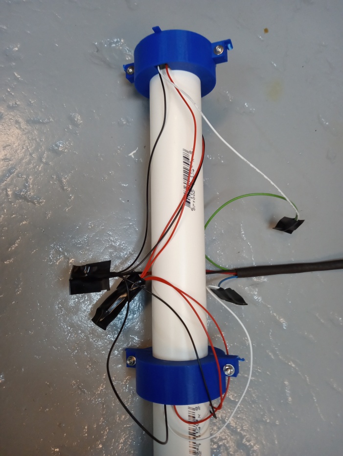
- One length of PVC pipe is sealed at its top to make a float that
slides inside another.
Exact diameters aren't critical.
The inner pipe should slide freely, but it should also be large enough to
reliably block the IR beams.
- IR emitter/detector pairs are mounted on opposite sides of the outer pipe,
peekng through holes drilled in the outer pipe's wall, of course.
- A rising water level raises the floating inner pipe eventually breaking the beam
between the upper IR emitter/detector.
The controller turns on the pump when the upper beam is broken.
- A falling water level lowers the floating inner pipe eventually
unbreaking the beam between the lower emitter/detector pair.
The controller turns the pump off when the lower beam is unbroken.
The hysteresis
minimizes power cycling and is parameterized by the separation between the
sensors (which is obviously constrained by the pipe lengths and hole depth).
This design has several specific merits:
- Almost any pair of standard plumbing pipes where one can contain
the other will do.
The only limiting factor might be the weight of the floating pipe.
- No sensors or wiring are in contact with water
except the pump's power cord which is designed to be submerged.
- The only moving part is a brain-dead floating pipe that's not attached
to anything!
No, hinges, shafts, wheels, pulleys or anything to get gummed up.
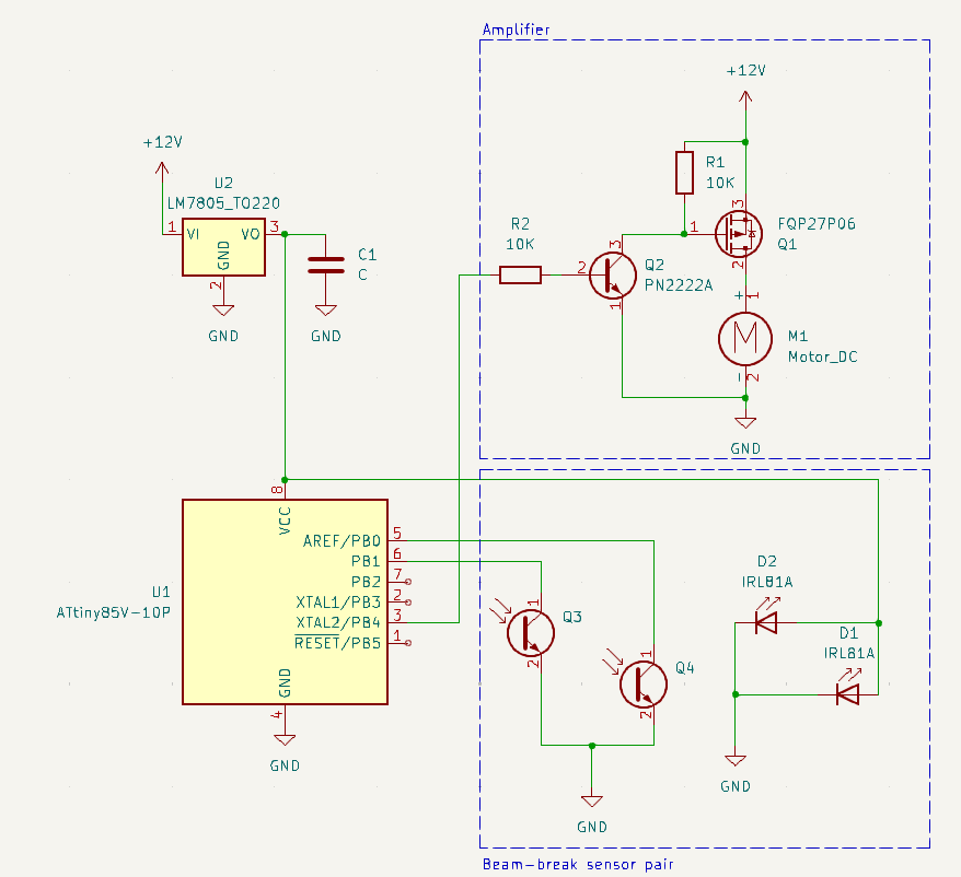
Electronics
Some electronics
were required to implement the hysteresis.
Dumb switches can't do it.
And since digital control is required, so is an amp, but the whole thing is
still fairly trivial.
An ATtiny85
running a few dozen lines of AVR assembly implements the hysteresis.
Yes, the ATtiny85 is overkill for this.
Some 74xx discrete logic and a latch could do it, too, but that would mean
using two or three chips instead of a single chip!
A MOSFET does what MOSFETs do so well: control large currents with the small
3.3 voltages out of μPs.
The PN2222A is just adding an extra bit of safety insuring nothing tries to
suck too much current out of the ATtiny85.
An LM7805 lets us power the whole thing from one of the ubiquitous 12V
power supply dongles (usually with 5.5mm barrel plug).
The dongle supplies 12V directly to the pump, and the LM7805 provides the 5V
that the electronics want.
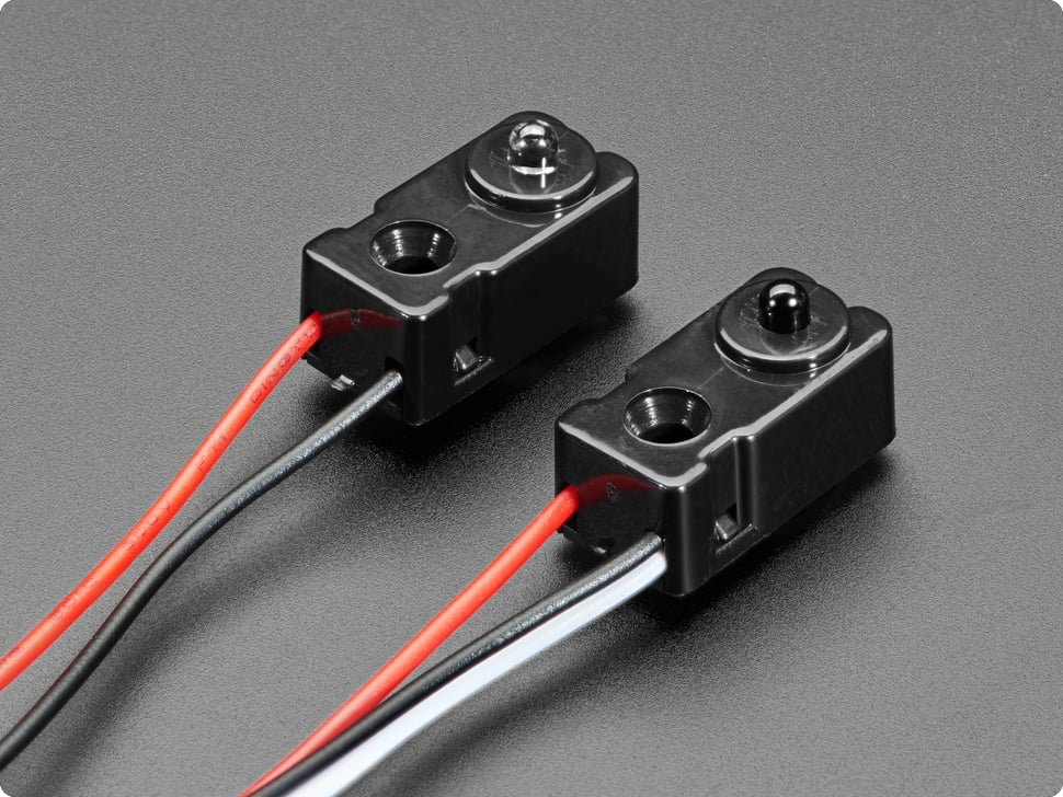
Incidentally, these
optical sensors intrigued me, but I already had the beam-break sensors on
hand (and they're cheaper).
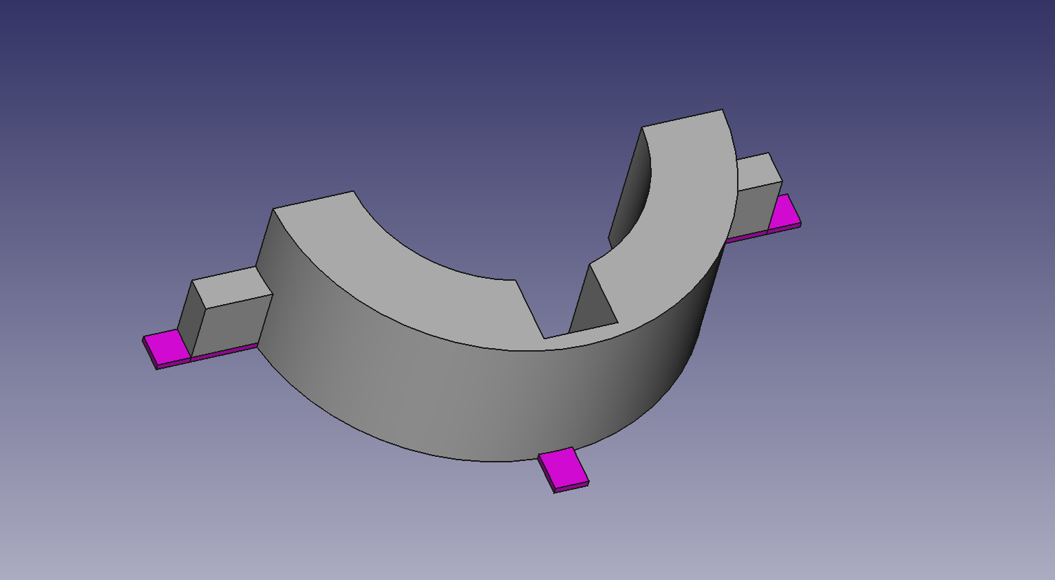
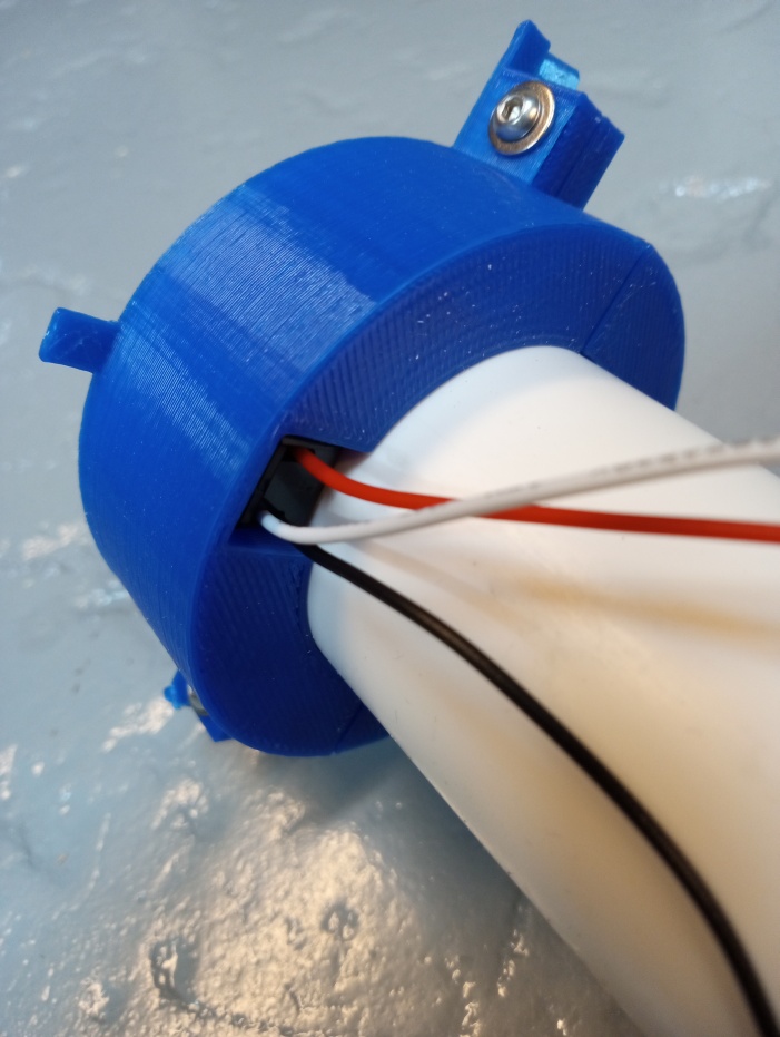
Mechanical
The IR emitter/detector pairs
I used are enclosed in rectangular cases for which I designed and 3D printed
mounts.
Pairs of these mounts clamp the Adafruit sensors against the outer pipe's
surface such that the domes of the emitter and detector just slightly
protrude into holes in the outer pipe so they can't slide down.
(The magenta tabs in the CAD image are a feature I typically add to
help pull a print off the printer bed.)
Really, the clamps were gratuitous;
one could also just tape the sensors in place!
The Build
A few things to consider if you build this yourself:
- The floating pipe ought to be relatively light as it will sit some depth
into the water (as shown in the animation).
- Make sure the power supply you use can provide the peak currents your pump
will draw at startup. (My Seaflo bilge pump peaks at around 5A.)
- More decoupling capacitors than the one I show in the
circuit might be required.
Details are here.
Let
me
 know if this inspires you!
Maybe I'll KiCad up a proper PCB and turn
the electronics (currently on a protoboard) into a proper product.
(Or maybe someone in Shenzhen will beat me to that.)
The mechanical aspects are too trivial to bother with especially since they are intended
to be improvised for unique situations.
know if this inspires you!
Maybe I'll KiCad up a proper PCB and turn
the electronics (currently on a protoboard) into a proper product.
(Or maybe someone in Shenzhen will beat me to that.)
The mechanical aspects are too trivial to bother with especially since they are intended
to be improvised for unique situations.